

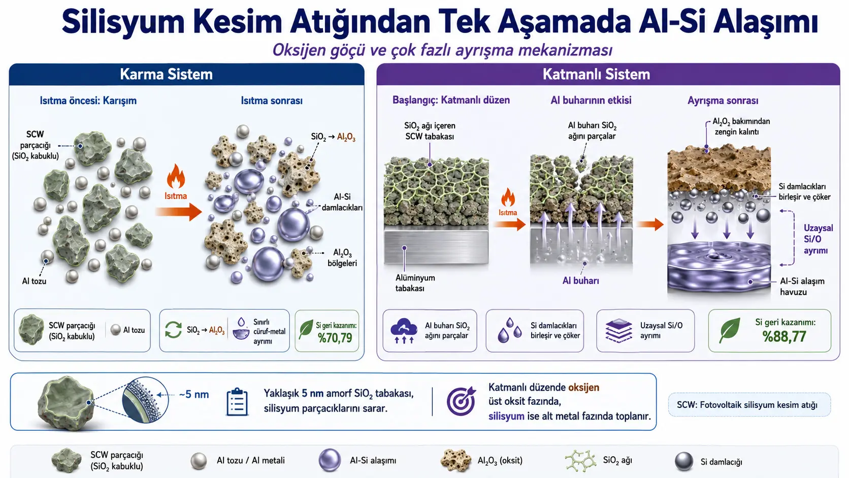
Ин таҳқиқот табдили мустақими fine silicon waste, ки ҳангоми diamond-wire cutting of photovoltaic silicon wafers ҳосил мешавад, ба aluminum-silicon alloy меомӯзад. Муайян шудааст, ки дар гирди silicon cutting waste particles қабати continuous amorphous SiO2 бо ғафсии тақрибан 5 nm мавҷуд аст. Ин oxide layer дар high temperature ба ҳам пайваста, oxygen-rich network ҳосил мекунад, ки molten silicon droplets-ро дар дохили худ нигоҳ медорад ва separation of metal and oxide phases-ро душвор месозад.
Researchers system-и homogeneous mixture of aluminum powder and silicon cutting waste-ро бо layered system, ки aluminum дар поён ва waste дар боло ҷойгир аст, муқоиса карданд. Дар mixed system at 1500 °C silicon recovery rate %70,79 ва bulk alloy yield %69 reported шуд. Дар layered system бошад, баъди treatment at 1500 °C for 60 minutes silicon recovery rate ба %88,77 ва bulk alloy yield ба %95,35 расидааст. According to proposed mechanism, Al vapor rising from molten aluminum at bottom ба upper waste layer penetrate карда, SiO2 network-ро ба looser phase rich in Al2O3 табдил медиҳад. Freed silicon droplets coalesce, move downward by gravity ва дар lower aluminum pool Al-Si alloy ташкил медиҳанд.
Although study is based on real melting and material-characterization experiments, it has not yet undergone peer review. Experiments are laboratory scale using approximately 8 g aluminum and 2 g silicon cutting waste. Mechanical properties, oxide inclusions, casting performance, energy consumption, emissions, cost and industrial scalability of produced alloys were not evaluated. In addition, there is an unexplained numerical inconsistency between reported %88,77 recovery value and value calculated using mass table and equation in article.
Аз нигоҳи Туркия: Proposed method offers a research-worthy approach for circular-production systems that could be established in Turkey by converting silicon cutting waste from photovoltaic manufacturing processes into aluminum casting alloys. Method aims to combine two separate high-temperature steps—first converting silicon to metallurgical-grade silicon and then alloying—into a single melting operation. However, for applicability assessment in Turkey, composition, oxide thickness, impurities and particle distribution of local waste should be determined; pilot-scale furnace tests, energy and argon consumption, aluminum loss, slag amount, alloy cleanliness, mechanical properties and economic feasibility should be independently studied. This study does not show method is directly low-cost or industrially ready in Turkey.
Чаро photovoltaic silicon cutting waste манбаи муҳим аст?
Crystalline silicon ingots are cut with diamond wires into thin wafers for photovoltaic cells. According to data cited in study, during cutting approximately %30–35 of crystalline silicon ingot can pass into cutting fluid as very fine particles. Resulting silicon cutting waste, abbreviated SCW, contains substantial silicon but is not a clean metal powder ready for direct use.
Waste can contain surface oxides, metallic impurities from cutting process and residual organic cutting fluids in addition to crystalline silicon particles. Uncontrolled disposal not only wastes valuable silicon but may also create fine-particle, water and land-pollution problems.
In conventional recovery approach, metallurgical-grade silicon is first produced from cutting waste, then this silicon is alloyed with aluminum in a second melting step. Examined study aims to combine these two high-temperature stages into one Al-SCW melting process.
Main research question чист?
Main question is how continuous SiO2 layer around silicon particles transforms during melting and how oxygen separates from metallic Al-Si phase.
Study specifically asks:
- In what chemical and structural form is oxygen present in initial silicon cutting waste?
- How does initial spatial arrangement of aluminum and waste affect alloy formation?
- In mixed and layered charging configurations, in which phases do silicon and oxygen concentrate?
- How does SiO2 layer hinder coalescence of Al-Si droplets and metal-slag separation?
- What role can aluminum vapor play in breaking oxide network?
Oxygen in silicon cutting waste дар кадом шакл аст?
Researchers examined oxygen content using XRD, FT-IR, XPS, SEM and TEM. No distinct crystalline oxide peaks were seen in XRD; detected crystalline peaks were attributed to silicon. In contrast, FT-IR spectrum showed bands corresponding to vibrations of Si-O-Si bonds.
XPS analysis showed oxygen exists as SiO2 and SiOx with lower oxidation states. These results are consistent with oxide phase being largely amorphous and therefore not appearing as a distinct crystalline phase in XRD.
SEM image in Figure 2 shows waste is mostly composed of fine, irregular, flaky particles. Most particle sizes are concentrated in 0–2 µm range. TEM image of a single particle shows crystalline silicon core surrounded by approximately 5 nm thick amorphous SiO2 layer.
| Silicon cutting waste property | Value or observation reported in study |
|---|---|
| Main particle size | 0–2 µm |
| Crystalline core | Elemental silicon |
| Surface layer | Amorphous SiO2 and SiOx |
| Approximate oxide-layer thickness | 5 nm |
| Reported elemental Si content | %79,79 by mass |
| Reported silicon oxide content | %15,43 by mass |
Чаро SiO2 layer alloy formation-ро душвор мекунад?
Oxide layer is not merely a thin surface film preventing direct contact between aluminum and silicon. At high temperature softened SiO2 layers of neighboring particles can join to form a three-dimensional continuous oxygen-rich network.
When silicon cores melt, liquid Si droplets remain trapped within this viscous oxide network. Researchers describe this as physical locking mechanism preventing droplets from coalescing under their own weight and moving downward.
Even in control experiment where pure silicon cutting waste was held at 1500 °C for 120 minutes, silicon recovery reportedly remained only around %60–70. SEM-EDS images showed liquefied silicon regions trapped within continuous Si-O-rich matrix. However repeat number, average and error range for these control experiments were not provided.
What raw materials were used?
Silicon cutting waste was supplied by Haobo Co., Ltd. in Jiangsu, China. Commercial aluminum powder with %99,85 purity by mass was supplied by Boyu Metal Co., Ltd. Waste was washed with ethyl alcohol before melting to remove residual organic cutting fluids.
In each experiment amount of silicon cutting waste was prepared as %20 of aluminum powder mass. Experimental masses in Table 4 are about 8,0 g Al and 2,0 g SCW.
Hydrofluoric acid and graphite powder are also listed in materials section. However uploaded version does not explain where and for what purpose these two materials were used in experimental workflow.
How were two different raw-material charging methods designed?
Mixed charging system
Treated silicon cutting waste and aluminum powder were homogenized in a ball mill for three hours. Mass ratio between grinding media and material was 4:1. Prepared mixture was placed in corundum crucible.
In part of microstructure and phase-separation experiments, homogeneous mixture was compacted into dense block by cold isostatic pressing at 300 MPa and then melted at different temperatures and times.
Layered charging system
In layered arrangement aluminum powder was placed at bottom of corundum crucible and silicon cutting waste above aluminum. Two materials were not mechanically mixed initially.
Prepared crucibles were placed in tube furnace, temperature raised at 5 °C per minute and experiments conducted under argon atmosphere. Products were cooled to room temperature together with furnace after treatment.
Overall results of mixed and layered systems
| Charging arrangement | Temperature | Bulk alloy yield | Silicon recovery rate |
|---|---|---|---|
| Mixed Al-SCW | 1000 °C | %0 | %0 |
| Mixed Al-SCW | 1200 °C | %58 | %54,98 |
| Mixed Al-SCW | 1500 °C | %69 | %70,79 |
| Layered Al-SCW | 1000 °C | %0 | %0 |
| Layered Al-SCW | 1200 °C | %0 | %0 |
| Layered Al-SCW | 1500 °C | %95,35 | %88,77 |
Mixed system produced alloy formation earlier at lower temperatures. Because aluminum and waste particles were in direct contact from start, aluminothermic conversion and transfer of silicon into liquid aluminum could begin at lower temperatures.
Layered system showed no distinct alloy formation at 1000 and 1200 °C. However when temperature reached 1500 °C, higher bulk alloy yield and silicon recovery than mixed system were obtained. Reported difference in silicon recovery between two systems is 17,98 percentage points.
Expression “significantly higher” in article is not based on a statistical test. Since sample repeats, error bars, standard deviation or p value are not given, results should be interpreted as numerical differences.
What did metallurgical-grade silicon control show?
Researchers performed control experiment using metallurgical-grade silicon powder instead of silicon cutting waste to demonstrate effect of oxide layer. When metallurgical-grade silicon and aluminum were melted at 1500 °C, both mixed and layered arrangements formed a single smooth-surfaced metal pool and no distinct solid slag layer was observed on top.
This observation supports that amorphous SiO2 layer in silicon cutting waste transforms a simple Al-Si alloying operation into a more complex process requiring chemical reduction and multiphase separation.
How do alloy and slag form in mixed system?
In mixed system aluminum and oxide-coated silicon particles are in close contact from beginning. When aluminum melts it directly reacts with SiO2 shell, oxygen transfers to Al2O3-rich phase and released silicon dissolves in liquid aluminum.
At low-temperature stage metallic Al-Si regions and oxygen-rich dark phases are dispersed within one another. As temperature increases diffusion of silicon into aluminum particles progresses and Al2O3-rich phase becomes more distinct.
At higher temperature small Al-Si droplets coalesce into larger metallic regions, while solid or semi-solid Al2O3 particles are pushed between and outside metallic droplets. This allows metallic phase growth, but complete metal-slag separation does not occur because initial distribution is very fine and homogeneous.
Effect of temperature in mixed system
Figure 4 shows dispersed Al, Si and oxygen-rich regions at low temperature and growing metallic phases with accumulated oxide regions at higher temperatures.
- Approximately 700 °C: Light-gray metallic regions containing Al-Si and surrounding oxygen-rich dark phases were observed. Part of silicon had not yet fully alloyed with aluminum.
- Approximately 800 °C: Silicon was found to distribute more regularly into aluminum particles, while oxygen-rich phase contained mainly Al and O.
- Higher temperature: Metallic droplets coalesced into larger regions and concentrated Al2O3 phase in separate regions.
Exact highest temperature of these experiments is inconsistent in source. Section text mentions 700, 800 and 1000 °C, while Figure 4 caption gives third condition as 900 °C. Therefore uploaded version does not allow determining definitively whether third microstructure image belongs to 900 or 1000 °C.
Effect of holding time in mixed system
Images comparing one, 20 and 40 minutes show metallic Al-Si phase volume grows with time and oxygen-rich and metallic phases separate more clearly. Silicon continuously transfers into aluminum matrix while in-situ formed Al2O3 phase accumulates in separate regions.
There is also inconsistency about temperature of these experiments. Explanatory text states experiments were conducted at 1000 °C, while Figure 5 caption states 900 °C.
Чаро layered system mechanism-и дигар дорад?
In layered arrangement liquid aluminum is at bottom of crucible and silicon cutting waste on top. Therefore initially there is no widespread liquid contact between two layers. Researchers propose Al vapor generated by high-temperature aluminum moves upward into porous waste layer.
Presence of Al in upper layer was supported by small Al particles and Al-O-rich debris observed on surfaces of large silicon-rich particles in samples taken at 1440 °C. According to researchers, gaseous Al undergoes gas-solid aluminothermic reaction with amorphous SiO2 shell and breaks continuous oxide network.
This explanation is mechanistic interpretation based on SEM-EDS, XRD and product morphology. Amount, pressure, flux or movement of Al vapor through waste layer were not directly monitored by gas-phase measurements.
Five-stage transformation observed in layered system
- Sintering of upper waste layer: Loose silicon cutting waste became denser brown block as temperature increased.
- Appearance of silicon droplets at surface: From about 1460 °C small spherical droplets appeared on surface of sintered block.
- Droplet growth: As temperature rose to 1485–1500 °C volume and number of spherical surface droplets increased.
- Formation and coalescence of Al-Si alloy: Droplets initially described as pure Si interacted with Al vapor or condensed liquid Al, transformed into Al-Si droplets and coalesced.
- Gravity settling: Sufficiently grown droplets passed through loosened Al2O3-rich upper layer and fell into Al-Si metal pool at bottom of crucible.
Temperature and time sequence in Figure 6 presents macroscopic appearance of these five stages in different samples. Therefore process was reconstructed by combining experiments stopped under different conditions rather than continuous real-time imaging of a single sample in furnace.
Which phases were found in upper layer at 1440 °C?
Brown sintered upper product at 1440 °C consisted of irregular large particles about 100–200 µm and small spherical particles attached to them.
| EDS point | Al, wt % | Si, wt % | O, wt % | Interpretation in study |
|---|---|---|---|---|
| A | 6,14 | 85,21 | 8,65 | Large silicon-rich particle |
| B | 94,16 | 4,00 | 1,84 | Small Al-rich spherical particle |
| C | 50,73 | 3,11 | 46,16 | Al-O-rich oxide debris |
Detection of Al in upper product despite no direct mixing between upper waste layer and lower aluminum pool is one main bases for interpreting that aluminum can be transported upward as vapor or condensed droplets.
How did droplets change between 1460–1500 °C?
EDS analysis of spherical droplets appearing at 1460 and 1485 °C reportedly identified them as approximately %100 Si. At this stage elemental silicon released from oxide network formed separate surface droplets.
In products held at 1500 °C for 30 minutes, spherical particles became alloy droplets containing Al and Si rather than only Si. Researchers explain this by absorption of increased Al vapor by silicon droplets or local alloying with condensed liquid Al.
When holding time reached 40 minutes and above, grown alloy droplets passed through porous oxide residue above and settled into lower metal pool. XRD analysis of upper layer showed high amount of Al2O3 along with small Al and Si peaks. Residual Al and Si were linked to small metallic particles trapped within slag network.
How did mass transfer progress in layered system?
| Condition | Upper-residue mass | Lower-alloy mass | Si in alloy |
|---|---|---|---|
| 1440 °C | 1,940 g | 8,006 g | %0,484 |
| 1460 °C | 1,292 g | 8,603 g | %9,24 |
| 1485 °C | 1,271 g | 8,701 g | %11,52 |
| 1500 °C, start of holding | 1,363 g | 8,583 g | %13,22 |
| 1500 °C, 30 minutes | 1,090 g | 8,837 g | %14,64 |
| 1500 °C, 40 minutes | 0,829 g | 9,174 g | %16,05 |
| 1500 °C, 60 minutes | 0,623 g | 9,296 g | %15,64 |
Decrease in upper-residue mass and general increase in lower-metal-pool mass and silicon content with increasing temperature and time support transfer of silicon from upper waste layer to lower metallic phase.
Si fraction in alloy reached highest level of %16,05 at 40 minutes and fell to %15,64 at 60 minutes. Despite this, total recovered silicon amount remained high because lower-alloy mass increased.
How was silicon recovery calculated?
Study defines silicon recovery rate by:
\[ R(\mathrm{Si}) = \frac{M_{\mathrm{alloy}}\,[\mathrm{Si}]_{\mathrm{alloy}}}{M_{\mathrm{SCW}}\,w(\mathrm{Si})} \]
Here:
- R(Si): Silicon recovery rate.
- Malloy: Mass of alloy obtained at bottom.
- [Si]alloy: Mass fraction of silicon in lower alloy.
- MSCW: Mass of silicon cutting waste initially used.
- w(Si): Mass fraction of elemental silicon in initial waste.
How was aluminum loss calculated?
Aluminum loss rate given by:
\[ L(\mathrm{Al}) = \frac{M_{\mathrm{Al}}-M_{\mathrm{alloy}}\left(1-[\mathrm{Si}]_{\mathrm{alloy}}\right)}{M_{\mathrm{Al}}} \]
Here MAl is initial aluminum mass and remaining terms represent mass and silicon fraction of lower alloy.
Study reports aluminum loss first increased during heating, reached %7,24 when 1500 °C was reached and decreased to %2,09 after 60-minute holding. Initial rise was attributed to aluminum vaporizing and reacting with SiO2 in upper layer; later decrease attributed to formed Al-Si droplets returning to lower metal pool.
Numerical inconsistency in silicon-recovery calculation
Abstract, conclusion and general comparison table report %88,77 silicon recovery for layered system. However using 9,296 g alloy mass, %15,64 alloy silicon, 2,003 g initial waste and %79,79 elemental Si fraction given for 1500 °C and 60 minutes in Table 4 in equation above yields approximately %90,97.
This difference may result from rounded values in table, use of different initial Si fraction in recovery calculation, or reporting error. Uploaded version does not explain difference, so %88,77 should be conveyed as reported study result while reproducibility issue is noted.
Oxygen pathways in mixed and layered systems
Mixed system
- Aluminum melts and directly contacts oxide-coated Si particles.
- SiO2 shell transforms in place into Al2O3-rich phase.
- Released Si dissolves in liquid Al and forms Al-Si droplets.
- As droplets coalesce, Al2O3 is pushed out of metallic phase.
- Initial fine dispersed structure limits complete slag-metal separation.
Layered system
- Lower Al melts forming metal pool, upper waste sinters.
- Al vapor moves into porous waste layer above.
- Al vapor transforms amorphous SiO2 network into looser Al2O3-rich structure.
- Released Si melts, coalesces as droplets and grows.
- Growing Si or Al-Si droplets descend by gravity to lower metal pool.
- Silicon concentrates in lower metallic phase and oxygen in upper oxide residue.
Figure 12 visually summarizes basic difference between systems. In mixed arrangement metal and oxide phases form dispersed within same volume, whereas in layered arrangement they accumulate in different parts of crucible partly due to initial geometry.
Strengths of study
- Photovoltaic silicon cutting waste used as real secondary raw material.
- Mixed and layered charging arrangements compared at same basic raw-material ratio.
- Oxide layer of waste examined by complementary XRD, FT-IR, XPS, SEM and TEM methods.
- Approximately 5 nm amorphous SiO2 shell directly shown by TEM.
- Macroscopic and microscopic transformations monitored with temperature and holding time.
- Control comparisons made using pure silicon cutting waste and metallurgical-grade silicon.
- Al, Si and O distributions evaluated by SEM-EDS maps.
- Masses of upper oxide residue and lower metal pool measured separately.
- Five-stage transformation and phase-separation model developed for layered system.
Main limitations of study
- Study is preprint not peer reviewed.
- Experiments are laboratory scale using approximately 10 g total charge.
- Independent experimental repeats and between-run variability not provided for most conditions.
- No mean, standard deviation, confidence interval, error bar, analysis of variance or p value.
- Only one silicon cutting waste source and one basic SCW/Al ratio studied.
- Different particle sizes, oxide thicknesses and impurity profiles not compared.
- Al vapor generation and transport through waste layer not directly measured.
- Gas-phase Al amount, vapor pressure and mass-transfer rate not determined.
- Complete chemical composition and metallic impurities of produced Al-Si alloy not reported in detail.
- Al2O3 inclusions, porosity and metal cleanliness in alloy not measured.
- Microstructure, primary Si morphology, grain size and solidification structure not examined in detail.
- No tensile strength, hardness, fatigue, wear or castability tests.
- Possible interaction between corundum crucible and product not evaluated.
- Argon consumption, energy requirement, slag amount and process emissions not calculated.
- No techno-economic analysis or life-cycle assessment.
- No industrial continuous-furnace or pilot-scale validation.
Reporting issues in source
- Third temperature of Figure 4 given as 1000 °C in section text and 900 °C in figure caption.
- Holding experiments in Figure 5 shown as 1000 °C in text and 900 °C in figure caption.
- Point numbers repeated in Table 2 column headings and mapping of points to temperatures not arranged clearly enough.
- Role of hydrofluoric acid and graphite powder listed in materials is not explained.
- Although FT-IR and XPS were used, model and measurement conditions of these instruments not provided in methods section.
- Number of experiments and raw results for %60–70 recovery range reported in pure SCW control not presented.
- Reported %88,77 silicon recovery cannot be exactly reproduced from Table 4 and stated initial Si fraction.
- No cost or energy comparison validating “low-cost” and “short-process” claims.
Which conclusions are supported?
- Silicon cutting waste particles have approximately 5 nm thick amorphous SiO2 surface layer.
- This oxide layer can join at high temperature to form oxygen-rich network that hinders separation of Si droplets.
- Aluminum can transfer oxygen from SiO2 phase to Al2O3-rich phase.
- Alloy formation began at lower temperature in mixed system than layered system.
- Layered system at 1500 °C produced higher bulk alloy yield and reported Si recovery than mixed system.
- In layered arrangement Si concentrated in lower metal pool and oxygen in upper oxide residue.
- Transport of aluminum to upper waste layer is associated with breakdown of SiO2 network.
- As holding time increased upper-residue mass decreased and lower alloy pool grew.
Which conclusions are not proven?
- Does not prove method will deliver same recovery rate at industrial scale.
- Does not show produced alloy meets commercial casting Al-Si alloy standards.
- Does not prove mechanical properties equal commercial products.
- Does not show layered method is lower cost than existing recovery technologies.
- Does not calculate total energy consumption as lower than two-stage industrial process.
- Does not prove Al vapor is sole or dominant oxide-breaking mechanism by direct gas-phase measurements.
- Does not show all silicon and oxygen in waste are completely separated.
- Does not validate lower environmental impact than existing methods with life-cycle data.
Усул ва бозёфтҳои таҳқиқот
Experimental-method summary
| Method component | Approach used in study |
|---|---|
| Study type | Comparative high-temperature melting and material characterization |
| Main raw material | Photovoltaic silicon-wafer cutting waste |
| Metal source | Al powder of %99,85 purity by mass |
| SCW/Al ratio | SCW equal to %20 of Al mass |
| Pre-cleaning | Washing with ethyl alcohol |
| Mixed-system preparation | Three-hour ball milling; media/material mass ratio 4:1 |
| Layered-system preparation | Al below, SCW above |
| Crucible | Corundum |
| Furnace | Tube furnace |
| Heating rate | 5 °C/minute |
| Atmosphere | Argon |
| Main temperature range | 700–1500 °C |
| Main layered-system condition | 1500 °C, 60 minutes |
| Mixture-compaction condition | 300 MPa cold isostatic pressing |
Characterization methods used
| Method or instrument | Property examined |
|---|---|
| BT-9300ST laser particle-size analyzer | SCW particle-size distribution |
| Transmission electron microscope | Crystalline Si core and approximately 5 nm amorphous SiO2 layer |
| XRD, PANalytical X’Pert Pro MPD-DY2094 | Identification of crystalline phases |
| Cu Kα radiation | Wavelength 0,15406 nm |
| FT-IR | Si-O-Si bond vibrations |
| XPS | Chemical states of Si, SiOx and SiO2 |
| Zeiss ULTRA PLUS FE-SEM | Particle and product micromorphology |
| EDS | Al, Si and O composition and elemental distribution |
| Macroscopic product examination | Metal pool, slag, droplets and layer separation |
| Mass measurements | Upper residue and lower alloy amount |
Experimental variables
- Initial charging geometry: Mixed or layered.
- Melting temperature: 700–1500 °C in different experiments.
- Holding time: From one minute to 120 minutes.
- Lower metallic phase: System containing aluminum or pure SCW control.
- Silicon source: SCW or metallurgical-grade Si control.
- Main outputs: Bulk alloy yield, Si recovery, Al loss, upper-residue mass, lower-alloy mass and elemental distribution.
Main quantitative findings
- Elemental Si content in SCW reported as approximately %79,79.
- Silicon oxide content reported as approximately %15,43.
- Amorphous SiO2 layer surrounding Si particles approximately 5 nm thick.
- In mixed system silicon recovery at 1200 °C was %54,98.
- In mixed system silicon recovery at 1500 °C was %70,79.
- In layered system reported silicon recovery at 1500 °C was %88,77.
- Bulk alloy yield in layered system given as %95,35.
- Upper-residue mass in layered system decreased from 1,940 g to 0,623 g.
- Lower-alloy mass increased from 8,006 g to 9,296 g.
- Si content of lower alloy was %0,484 at 1440 °C and reached %16,05 at 1500 °C and 40 minutes.
- Al loss reached %7,24 when 1500 °C was attained and decreased to %2,09 after 60 minutes.
- In pure SCW control highest reported Si recovery at 1500 °C and 120 minutes remained about %60–70.
Statistical assessment
Study does not consistently provide numbers of experimental repeats; no standard deviation, standard error, confidence interval, error bar, analysis of variance or p value is presented. Therefore difference between %88,77 and %70,79 is a numerical difference under experimental conditions, not a result of statistical significance.
Mechanism proposed by study is based on consistency among macroscopic samples collected at different temperatures and times, SEM-EDS element distributions, XRD phases and mass changes. Some processes such as Al-vapor transport and droplet settling were not measured directly and in real time, but inferred from observed products.
Ёддошти манбаъ ва усул
Full original title: Oxygen Migration and Multi-Phase Separation Mechanism for One-Step Synthesis of Al-Si Alloys from Photovoltaic Silicon Cutting Waste
Authors and correct order: Donghui Wei, Kaiyang Liu, Xinpeng Liu, Tianding Li, Penghui Guo, Xiangdong Xing
Equal first author or equal contribution: No equal-first-author or equal-contribution information.
Corresponding authors: Penghui Guo and Xiangdong Xing
Institutional affiliations:
- School of Metallurgical Engineering, Xi’an University of Architecture and Technology, Xi’an 710055, China
- Guangxi Beibu Gulf New Materials Co., Ltd., Beihai 536017, China — second affiliation of Kaiyang Liu
ORCID: No ORCID information for authors in uploaded version.
Journal: Not published in peer-reviewed journal.
Original journal publisher: None.
Publication platform: SSRN
Publication date: 28 July 2026
Source type: Preprint containing experimental metallurgy, waste recovery and phase-transformation research
Peer-review status: Study has not undergone peer review. Every page of uploaded version contains warning that preprint is not peer reviewed.
Official publication link:Official SSRN preprint page
Funding: Study states support from National Natural Science Foundation of China 52504370, Shaanxi Provincial Natural Science Basic Research Program 2025JC-YBQN-516 and Jiayuguan City Science and Technology Bureau 24-02 projects.
Ин шарҳи тоҷикӣ бо examining text of uploaded study, experimental schematic, XRD, FT-IR and XPS results, TEM and SEM images, EDS elemental maps, macroscopic crucible photographs, four tables, two mass-transfer equations, pure SCW and metallurgical-silicon control experiments and proposed mechanism schematic омода шудааст. Scientific content is based only on uploaded study; external sources used only to verify SSRN date, DOI and bibliographic identity.
Main limitations are lack of peer review, laboratory scale, missing experimental repeats and statistical uncertainty, no direct measurement of Al-vapor transport, no study of mechanical and casting properties of alloy, absence of energy-cost analysis and source inconsistencies in some temperatures and recovery calculations. Results offer a promising mechanism and laboratory-scale recovery approach but do not by themselves prove industrial applicability.
Шарҳ гузоред
Нишонии почтаи электронии шумо нашр намешавад. Майдонҳои ҳатмӣ бо * нишон дода шудаанд